
Views: 500 Author: Curry Publish Time: 2025-08-21 Origin: https://www.microductcoupler.com/
With the rapid development of urban construction, urban pipeline resources are becoming less and less, cost is raising up for open road, road management and urban noise restrictions increased construction costs for telecommunications operator. FCST is offering professional fiber blowing solution and related products. Including products for backbone, LAN, pipeline expansion and FTTX network.
Blowing System from FCST Cable provides numerous advantages over conventional fiber optic systems, including increased flexibility for the designers of fiber optic networks as well as significant and measurable time, cost and service benefits to the network throughout its life cycle.
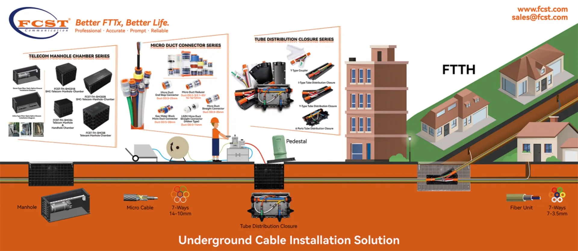
FIG1-Underground Cable Installation Solution
Pulling Method VS Air Blowing Method
Optical fiber cables for telecommunication application have been installed in pipes/ducts for many years. The installation process is influenced by local conditions, local climate, customer’s existing procedures, and customer requirements. There are two basic methods of cable installation in a preinstalled duct – Pulling method and Blowing method. The cable installation method is selected based on site conditions and availability of machinery & resources. Table 1 shows a comparison between the two installation methods.
Table 1 : Comparison between Pulling and Blowing methods
Pulling Method | Blowing Method |
Pulling rope pre-installed | No pulling rope to install |
Equipment and manpower at two sides | Equipment and manpower at one side |
High sidewall forces on cables and ducts may lead to cable damage | Forces on cable and duct can be monitored and controlled and minimal chance of cable damage |
Mainly manual pulling is practiced. | Large compressor and/or hydraulic power pack at one side |
Machine pulling needs one hydraulic power pack Mainly used for straight duct route | Preferred for duct route with multiple bends and undulations |
Suitable for short distance (few 100m) installation | Preferred for long distance (over 2km) installation |
In the actual Construction, we have obtained some reliable data by taking the laying of 1000m optical cable as an example. Please refer to Table 2: Construction Cost Comparison Table for details.
Table 2:Construction cost comparison table
Blowing Method | Pulling Method | |
Installation Time | 12 minutes | 60 minutes |
Manpower Needs | 2~3 people | 5~10 people |
Installation lengths | 1000m | 1000m |
Installation Rate | 60~85 m/min | 15 m/min |
Overall, blowing method is preferred over traditional pulling method due to savings in manpower & installation time and improved installation efficiency, particularly in longer ducts with multiple bends and undulations. FCST has accumulated many years of experience, cable installation by blowing method and its best practices are explained.

FIG2-Pulling Method VS Air Blowing Method
Microduct Installation
There are primarily four ways to install direct buried microducts:
Using a machine or hand to excavate an area and install them directly into the ground.
Placing it into a slot-cut or micro trench.
Using a mole plow.
Integrating it into an existing duct.
Before you begin any of these installations, you will want to use a manufacturer-supplied tube cutter to cut the microduct. Do not use any other cutting tool. Next, you need to make sure a sealing plug covers both ends of the microduct. Putting this in place will prevent any water or dirt from contaminating the duct and possibly causing damage. Finally, you want to check to see if you've trapped the drawcord with the sealing plug.
Micro Trench Installations
You'll need to use a micro trench if you need to install the microduct into a hard surface like a road or sidewalk. In these sorts of installations, you will hollow out a small trench in the surface, then use it to install the microduct wand cabling.
Clear all sides of the slot trench of any kind of debris. Along with clearing debris, you'll want to make sure to dry the trench if any liquid has entered it.
Level the bottom of the trench so the microduct can sit flat. Along with flattening the trench, try to avoid including any bend in the ducts. Following both of these tips will make the microduct easier to install.
Protect the microduct by including a shallow layer of soft filling at the bottom of the trench to avoid damage from stones. While you backfill, make sure to do so above the microduct to prevent harm. If you're especially concerned about damage, you can install a backer rod above the backfill.

FIG4-Micro Trench Installations
Mole Plow Installations
A mole plow attaches to a tractor or excavator to cut into the ground with speed and precision. While the plow opens the ground, it will feed the microduct into it.
Make sure the ground is even, so the microduct stays level.
Check that any bends in the route are smooth and wide.
Only use a mole plow when no hard surfaces are present.
Use a vibrating plow if there are roots and small stones present.
Select a plow that holds the microduct with it. Without the machine automatically placing it in the hole, you'll leave it vulnerable to damage.

FIG4-Micro Trench Installations
In-Duct Installations
If you already have larger ducts installed, you'll need to take several steps before you can install the microduct.
Check that there's enough space in the duct.
Compensate for the stretching that will occur as the microduct goes into the duct by letting there be some extra length.
Ensure there's enough space for the microduct to expand if the temperature is high.
Do not restrain the microduct until after 24 hours have passed. This wait will allow for the microduct to reach the same temperature as the jointing chamber and duct.
Avoid the microduct twisting while it gets pulled into the duct by using a swivel.
Distribute the pulling force over the initial section of the microduct with a pulling sock.

FIG6- In-Duct Installations
Blown Fiber Installation Method
Before the cable placing operation begins, the microduct system should be checked to be assured the cable’s minimum bend radius is not violated during handling, feeding, placing, and final positioning. The equipment and all pressure fittings should be checked. The placing engine should be checked to confirm that the tension and compression limits matching the cable being placed have been properly and accurately set. Radios should be checked to confirm that all manned positions along the right-of-way are in communications and prepared to start the placement. FIG1 shows a typical unassisted microduct cable jetting operation.

FIG7 – Cable Jetting Schematic Showing Placement Without Intermediate Assist
All transitions into and out of manholes shall be direct and smooth, not violating any of the cable’s mechanical or geometrical limits.
Air pressures and hydraulic pressures shall be set according to the placing engine manufacturer’s instructions. The operation of the placing engine during placement shall follow its manufacturer’s instructions.
The placing operation shall begin slowly and continue at the slow speed until it is clear that the placing operation is progressing smoothly. The placing speed can be increased gradually until the operation reaches a fast, but completely under control speed. Speeds from 30 to 60m/min (100-190 ft/min) or more can be reached depending upon the experience of the crew and the geometry of the placing route. FCST and the placing engine manufacturer recommend that the placing operation be performed at a safe and controllable speed.
Bidirectional Figure-8 Procedure
A placing plan listing the pulling locations, intermediate assist, and figure-8 locations should be developed during a pre-survey of the placing project. The placing plan will indicate the cable length to be coiled at the “figure-8” point.
For bidirectional placing operations a convenient intermediate point is selected for the figure-8 location. It should be near mid-span and, if possible, the duct section in both directions out from the figure-8 manhole should be placeable in a single operation.
Cable is jetted toward the intermediate figure-8 manhole following the jetting procedure outlined above. All cable is pulled off the reel with the excess cable figure-8 in a coil about 10 meters long at the intermediate figure-8 manhole. The figure-8 of the cable shall be done carefully, in a safe location free from access by the public.
Sufficient cable shall be left in the initial cable feed manhole to complete the splice to its neighboring cable and to provide cable slack for future maintenance operations.
After all cable has been pulled off reel and the excess cable figure-8, the pulling engine shall be moved to the figure-8 manhole and set up to complete the cable jetting operation from the figure-8 coil at the intermediate figure-8 manhole.
The figure -8 coil must be carefully turned over (“flipped”) so that the cable that was on the bottom is now on top. This cable coil “flip” will enable cable to be fed off the top of the coil to the far manhole to complete the placing operation.
Also special accessories are available for figure-8 handling which could reduce the number of manpower and total installation time.
The final segment of microduct will be jetted from the figure-8 manhole to the far end manhole. The jetting operation shall be conducted as described above. As always, the encasing conduit, sub-duct, innerduct, or microduct must be lubricated prior to the start of any placing operation following the lubrication schedule. Once the placing operation begins, lubrication must continue to be applied to the cable being jetted as it is placed.

FIG8-Bidirectional Figure-8 Procedure
Intermediate Assist
A placing plan determining pulling locations, including the intermediate assist location should be developed during a pre-survey of the placing project. FIG3 shows a cable jetting operation with intermediate assist.

FIG9-Intermediate Assist
For intermediate assist placing operations, a convenient intermediate point is selected as the intermediate location. It should be near mid-span and, if possible, the duct section in both directions out from the intermediate assist manhole should be placeable in a single operation. The area around the intermediate assist location should be capable of staging the ground support equipment (air compressor and hydraulic pump)for the placing engine.
For an intermediate assist procedure to be successful, the placing engines (primary and assist engine) need to be coordinated, so compressive forces do not build up causing the cable to buckle or kink. The assist placing engine manufacturer’s instructions to operate the engine as an assist engine in tandem with other placing engines should be followed.
Once the cable has been placed, sufficient slack cable should be provided on each end of the cable route to enable the splice to be made to the adjoining cable and to store the standard amount of slack at each splice required by the end-user of the cable for maintenance operations. Also, sufficient slack must be provided in intermediate manholes to rack the micro-duct and cable along the sides of the manhole, out of the way from harm and still have sufficient slack stored to accommodate the end-users requirements.
All ducts should be plugged at the conclusion of the placing operation. If a cable has been pulled into the duct, the duct plug should be sized for both the ID of the duct and the OD of the cable.The microduct shall be left intact through intermediate manholes during placing and racking, whenever possible unless the micro-duct was removed to enable intermediate assistance or a portion of the cable is branched off the cable route being placed.
Typically, a cable coil will be placed in a manhole or hand-hole to provide extra cable in the event of network damage or extra cable for splicing fibres. In certain environments, it may be determined that cable protection for the coiled slack is required due to the threat of rodent damage.If possible, protect any slack coils with split flexible conduit and store the coil in a safe position in the manhole or hand hole.
![]() Microduct Burial Depth Installation Instructions
Microduct Burial Depth Installation Instructions
Silicon Duct /Micro duct(DI) shall be constructed on a good foundation and must be manually reinforced in unstable soil.
The Angle between the center of the curved pipe should be as small as possible to reduce the lateral pressure when laying the cable.
Silicon Duct /Micro duct(DI) Minimum bending radius of duct laid, shall not be less than 1m.
The interface section of Silicon Duct /Micro duct(DI) shall be straight and free of burrs and shall be connected with matching sealing couplings.
The outside of the connector should be waterproof.
Special plugs should be used to seal both ends of the Silicon duct(DI) and prevent mud and water from entering the plastic duct during duct installation.
Silicon Duct /Micro duct(DI) should be used appropriately, and small duct or cable should not take up large outer protective duct, thereby reducing duct utilization.
Commonly used Silicon Duct is 40mm to 50mm in diameter and has good railing proof performance so that no special railing can be used.
The protective measures of air blowing pipe ditches and the setting of marker stones shall be carried out according to the relevant standards issued by the Ministry.

FIG10- Soil cross section
The depth of the Silicon Duct /Micro duct(DI) should be determined in the following table according to factors such as soil and environmental conditions.
No. | Paved lot and soil quality | Buried depth (m) |
1 | Common soil, hard soil | ≥1.0 |
2 | Semi-stony (gritty soil, wind fossils, etc.) | ≥0.8 |
3 | All stone, fluid sand | ≥0.6 |
4 | Suburbs, towns and villages | ≥1.0 |
5 | Urban streets | ≥0.8 |
6 | Crossing railway (from subgrade surface), highway (from pavement base) | ≥1.0 |
7 | Middle divider and shoulder of high - grade highway | ≥0.8 |
8 | A ditch, canal, pond | ≥1.0 |
9 | The river | Same as the requirements for underwater cable burial depth |

FIG11- Cross section of highway microduct
Microcables For Duct Installation-Fill Ratio, Duct Packing Density
Normally, micro-duct cables are jetted into an appropriately sized micro-duct. To insure that the jetting operation can be done efficiently, micro-duct should be selected to have some space between its inner diameter (ID) and the cable it contains. The recommended fill ratio has been empirically determined from actual jetting experience. It varies depending upon the length of the cable, the number and severity of the bends in the microducts, and the air pressure used. Using the following formula for FILL RATIO, the fill ratio should be no greater than 60 to 70%, although cables have been successfully jetted at higher fill ratios using higher air pressures.
FILL RATIO = (d⊃2;/D⊃2;) × 100
Where:d = outside diameter of cable and,
D = inside diameter of microduct

FIG12- FILL RATIO
This fill ratio should assure sufficient air movement and jetting force can be developed to enable the cable to be placed in its microduct. At very low fill ratios, the placing operation is less effective than at a greater fill ratio. The same formula can be used for microducts being jetted into innerducts or sub-ducts.
Based upon the fill ratio formula, above, a Fill Ratio of approximately 60 to 70%, and empirical data from previous field experience the information in Table 3 has been assembled to show the number of different size microducts that can be field installed in standard sized innerduct.
Table 3 - Micro-Ducts That Can Be Field Installed in Innerduct
Innerduct Nominal Diameter(in) | 12/10mm Microducts | 10/8mm Microducts | 7/5.5mm Microducts |
3/4 | None | 1 | 3 |
1 | 2 | 3 | 5 |
1 1/4 | 4 | 5 | 10 |
1 1/2 | 6 | 8 | 15 |
2 | 8 | 10 | 20 |
Using a 60 to 70% maximum fill ratio, each microduct is sized to accept cables up to a maximum diameter, unique to the ID of the microduct in which it is placed. Table 4 relates this unique maximum diameter for each microduct to the fibre range of Sterlite Micro DUCT-LITE cables encompassed by this microduct size.
When cables are installed into conduit or innerduct, the maximum cable diameter attempted / recommended will normally not exceed 50 to 60% of the conduit or innerduct ID.
Cable Jetting Construction Guide-Construction Step
After a lot of experience accumulation, FCST sorted out a construction step flow chart, hoping to help you.


